This tutorial shows how to assemble Bevel Gears (that are imported) in SpaceClaim. These are typically used to transmit motion (and power) in intersecting shafts. They are also used in differential of vehicles, for transmission of power to the wheels.
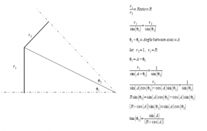
When bevel gears are imported inside SpaceClaim, we need to define Gear Condition/Constraint between them, which is done by selecting two conical surfaces. The main task is to find out these mating cones. The following diagram shows the equations of determining the apex angle (actually half the apex angle) of cones, given the ratio R1/R2 = N1/N2 (ratio of number of teeth). Once the angles are found, conical surfaces are drawn and gear condition is defined between them.
In the video tutorial below:
- We have imported a Bevel Gear Assembly from GrabCAD.
- The revolute joints (consisting of a Align condition + Tangent condition) are defined so that gears have a freedom to rotation (degree-of-freedom) about their axes.
- The pitch cones are determined in the form of surfaces (which do not add up to the mass of the components)
- Gear condition is defined between them.
- One of the bevel gears is rotated and the other rotates due to meshing.
- Go to SC-Motion. Gear conditions are made use of in the solver and simulation is done.
The SpaceClaim assembly file (with Gear condition defined) can be downloaded here.
The video tutorial can be downloaded here
We have similar tutorials for External Gears, Internal Gears, Rack and Pinion, and Worm Gears.
