PDF Export Addin for SpaceClaim

SpaceClaim is a very good software for direct modeling and making very quick prototype models. Once 3D models are made, sometimes their 2D DrawingSheets need to be exported as PDF files and sent to others for review or for fabrication etc. One SpaceClaim user approached us to develop an addin for him with the following functionality:

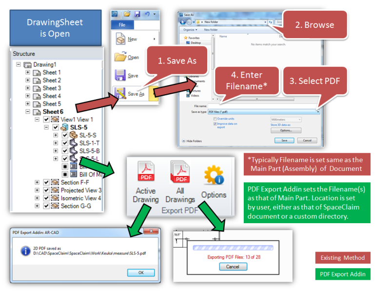
  • PDF file should be saved of a DrawingSheet
  • The file-name should be same as that of the main part of the DrawingSheet
  • The file location (directory) should be same as that of the SpaceClaim file

We created the addin for him and it has been of great utility.

Then, we realized that this is indeed a generic problem for other SpaceClaim users as well. After some exploration here and here, we have developed and launched “PDF Export Addin for SpaceClaim”. Apart from the features of our earlier addin, we have other features such as

  • Option to save the PDF file either in directory containing SpaceClaim file or a custom directory chosen by the user
  • Ability to “Export All” DrawingSheets of the SpaceClaim file (that is open).

The image below explains the Problem (Red Arrows and Callouts) and Solution using PDF Export Addin (Green Arrows)
The addin is available for free evaluation (7 days). Please feel free to download and try it. We are already getting some feature requests from a couple of SpaceClaim users and we hope to make them available in coming releases. Please post your suggestions/issues below as comments, we shall respond to them.
Equations for Joint Motion in SC-Motion 2012

SC-Motion, a motion and dynamic simulation addin inside SpaceClaim has abilities to perform motion (kinematic) and dynamic simulation on SpaceClaim assemblies. The motion at the joint can be a rotation or a translation. These can be supplied as Equations as well, which is covered in the tutorial below (The embedded tutorial file can downloaded here )

A video with example motion equations is below. (The video can be downloaded here )

All the SpaceClaim assemblies and the corresponding motion equations can be downloaded here. The zip file further contains six zip files. Each of these contain SpaceClaim file and a .txt file with equation (for reference).


Trace of a point using SC-Motion in SpaceClaim

SC-Motion is capable of a lot of things (kinematics and dynamics) and we have been adding new features every now and then. Our latest update is to trace a point on a link as it moves in a simulation. One can also use a custom point to plot kinematic data (position, velocity and acceleration).

In this tutorial, we are going to see how to trace an ellipse (and circle) in an Elliptical Trammel assembly.  Please follow the steps below:

  1. Open Elliptical Trammel assembly (.scdoc )
  2. Insert “Origin” (User Coordinate System or a Marker) on handle. By default, the origin is listed at assembly level. Rename it as “UCS1” and  move it to “handle” by dragging and dropping it.
  3. Start “SC-Motion”. UCS1 is listed as a marker under Components>Handle.
  4. Right click on UCS1 and “Enable Trace”. Optionally trace color can be set.
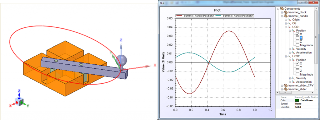
  5. Simulate (with defined joint rotation) and see the trace drawn during the animation (It actually draws an ellipse, hence the name)
  6. To add more tracepoints, go back to SpaceClaim and insert another “Origin”. Rename it as UCS2 and move it under Handle component.
  7. Come back to SC-Motion, UCS2 is automatically added under Components>Handle. Right click and enable trace.
  8. Simulate and animate and now you can see an ellipse and circle drawn together !!!
  9. More tracepoints (in the form of markers) can be added.
  10. Plot of these custom markers’ origin can be seen in the form of their position, velocity and acceleration.

The assembly file with trace markers enabled can be downloaded here.

 The video tutorial can be downloaded here

Assembly of Vertical Engine in SpaceClaim and its Simulation

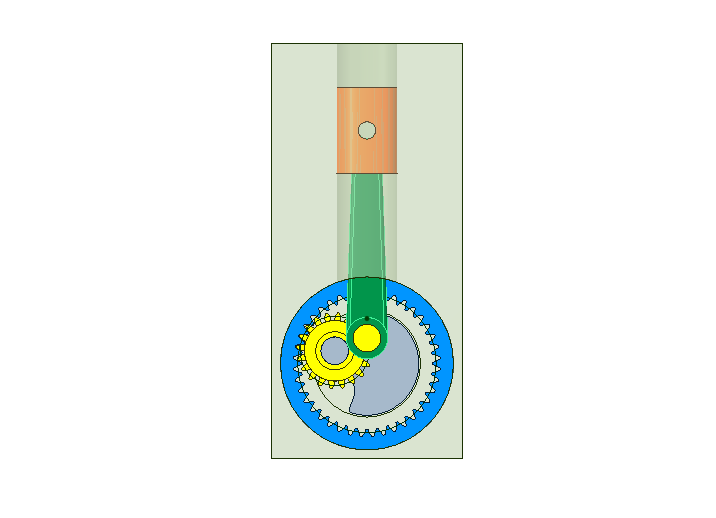
In this tutorial, we import a Vertical Engine (Concept) assembly from GrabCAD. The beauty of this concept is that the connecting rod always remains vertical and the crank is in the form an internal gear.

In the video tutorial below:

  1. We have imported assembly from GrabCAD inside SpaceClaim.
  2. Define assembly conditions between different components
  3. Draw pitch cylinders for Internal Gears. More details can be seen at our earlier tutorial.
  4. We have just defined a Gear condition between the pitch cylinders and the gear meshing is perfect. In general, we should also assign a Tangent condition between the same two pitch cylinders (surfaces).
  5. We observe that the cylindrical hole for the piston to go up and down is not at the right place. We move this hole very easily inside SpaceClaim to its right place.
  6. Move the crank and see the piston go up and down.
  7. Start SC-Motion and simulate the motion by defining rotation at the crank.

The SpaceClaim assembly file (with assembly conditions) can be downloaded here.
The reason why the connecting rod goes up and down is stated here. The excerpt is
If you place a gear inside another gear, with the internal gear having a tooth count of half the ring gear’s tooth count, any point on the pitch diameter of the inside gear will move back and forth in a straight line.

Bevel Gears Assembly and Simulation in SpaceClaim

This tutorial shows how to assemble Bevel Gears (that are imported) in SpaceClaim. These are typically used to transmit motion (and power) in intersecting shafts. They are also used in differential of vehicles, for transmission of power to the wheels.

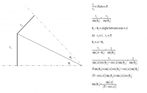
When bevel gears are imported inside SpaceClaim, we need to define Gear Condition/Constraint between them, which is done by selecting two conical surfaces. The main task is to find out these mating cones. The following diagram shows the equations of determining the apex angle (actually half the apex angle) of cones, given the ratio R1/R2 = N1/N2 (ratio of number of teeth). Once the angles are found, conical surfaces are drawn and gear condition is defined between them.

In the video tutorial below:

  1. We have imported a Bevel Gear Assembly from GrabCAD.
  2. The revolute joints (consisting of a Align condition + Tangent condition) are defined so that gears have a freedom to rotation (degree-of-freedom) about their axes.
  3. The pitch cones are determined in the form of surfaces (which do not add up to the mass of the components)
  4. Gear condition is defined between them.
  5. One of the bevel gears is rotated and the other rotates due to meshing.
  6. Go to SC-Motion. Gear conditions are made use of in the solver and simulation is done.

The SpaceClaim assembly file (with Gear condition defined) can be downloaded here.

 The video tutorial can be downloaded here

We have similar tutorials for External Gears, Internal Gears, Rack and Pinion, and Worm Gears.

Worm Gear Assembly and Simulation in SpaceClaim

This tutorial shows how to assemble Worm Gears (that are imported) in SpaceClaim. These are typically used for very high reduction of speed in shafts (hence very high gain in torque) when the space is limited. The axes of shafts are skew and the angle between them is usually 90 degrees.

Update (July 20, 2012): Considered number of starts/threads in the worm in the equations.

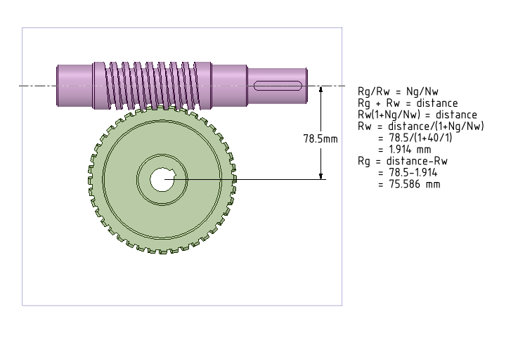
When a worm gear assembly is imported inside SpaceClaim, we need to define Gear Condition/Constraint between them, which is done by selecting two cylindrical surfaces. The main task is to find out the radii of these mating cylinders (also known as Pitch Radius). The following diagram shows the equations of determining the radii Rg (Radius of gear) and Rw (Radius of worm) of the two cylinders, given the number of teeth in the gear(Ng), number of threads/starts in the worm (Nw) and the distance between the axes of the gears. We have two equations with Rg and Rw and solving for Rg and Rw is simple.


In the video tutorial below:

  1. We have imported a Worm Gear Assembly from GrabCAD.
  2. The revolute joints (consisting of a Align condition + Tangent condition) are defined so that worm and gear have a freedom to rotate (degree-of-freedom) about their axes.
  3. The pitch cylinders are determined in the form of surfaces (which do not add up to the mass of the components)
  4. Gear condition is defined between them.
  5. Worm is rotated and the gear rotates due to meshing.
  6. Go to SC-Motion. Gear conditions are made use of in the solver and simulation is done.

The SpaceClaim assembly file (with Gear condition defined) can be downloaded here.

 The video tutorial can be downloaded here

We have similar tutorials for External Gears, Internal Gears, Rack and Pinion and Bevel Gears.

Rack and Pinion Assembly and Simulation in SpaceClaim

This tutorial shows how to assemble Rack and Pinion (that are imported) in SpaceClaim. These are typically used to convert the rotary motion applied to the pinion into translatory motion of the rack.

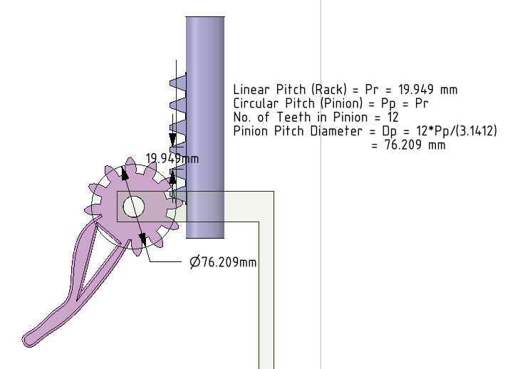
When the rack and pinion assembly is imported in SpaceClaim, we need to identify the pitch circle (or cylinder) of the pinion and the pitch line (or plane) of the rack.  We then need to define “Gear Condition” between the cylinder and plane.  The following diagram shows the equations for determining the pitch circle diameter of the pinion. Once it is found, a line tangent to this circle and parallel to the rack surface is the pitch line. The circle and line are then pulled to make surfaces, between which Gear Condition is defined.

In the video tutorial below:

  1. We have imported a Rack and Pinion Assembly from GrabCAD.
  2. Define revolute joint (consisting of Align condition + Tangent condition) between pinion and the base part.
  3. Define prismatic/translatory joint (consisting of Align condition + Angle condition) between rack and the base part.
  4. Determine the pitch circle of the pinion. Draw a line tangent to this circle and parallel to the rack surface.
  5. Make the circle and line as “Construction lines”, so that we can get surfaces when these are pulled. (which are without mass).
  6. Gear condition is defined between cylindrical and planar surfaces.
  7. Pinion is rotated about its axis and the rack translates due to proper meshing.
  8. Go to SC-Motion. Define joint rotation for pinion and its rotation results in the translation of the rack.

The SpaceClaim assembly file (with Gear condition defined) can be downloaded here.

 The video tutorial can be downloaded here

We have similar tutorials for External Gears, Internal Gears,  Worm Gears and Bevel Gears.

Internal Gears Assembly and Simulation in SpaceClaim

This tutorial shows how to assemble gears (that are imported) in SpaceClaim. The type of gears considered is “Internal Gears”. These are typically used in planetary gears. This is in continuation of our earlier tutorial on assembling external gears in SpaceClaim. Please go through it to catch up in this tutorial.

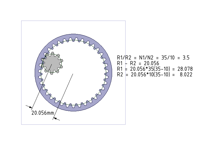
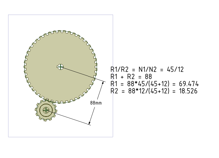
Here, we have to find the pitch radii of the internal gear (larger number of teeth) and the external gear (lesser number of teeth). Then, Gear Condition needs to be defined between these pitch cylinders for perfect mating of the gears at hand. The following diagram shows the equations of determining the radii R1 and R2 of the two cylinders, given the number of teeth in the gears and the distance between the centers of the gears. We have two equations with R1 and R2 and solving for R1 and R2 is straight forward.

In the video tutorial below:

  1. We have imported a Gear Assembly from GrabCAD.
  2. Make the internal gear as fixed component and define Tangent condition between the mating planes of the gears.
  3. The pitch cylinders are determined in the form of surfaces (which do not add up to the mass of the components).
  4. Gear condition is defined between them.
  5. Edit the property of Gear condition “Reverse Rotation Direction” so that the sense of rotation for external gears and internal gears are same (as opposed to that between two external gears, where the sense of rotation is reversed).
  6. Try to move the external gear. It does not move as required. This is because, the gear condition only makes sure that the relative rotation of the gears are as per the ratio of number of teeth [This is as of SpaceClaim 2012 version].
  7. Define a Tangent condition between the same set of pitch cylinders. Move the external gear and it follows the desired path. This needs to be defined so that external gear and internal gear mesh perfectly.
  8. Go to SC-Motion. Since we do not have a revolute joint to define rotation, we have defined Gravity for the assembly and let the external gear move due to the action of gravity (Dynamic Simulation)

The SpaceClaim assembly file (with Gear condition defined) can be downloaded here.

 The video tutorial can be downloaded here

We have similar tutorials for External Gears, Rack and Pinion, Worm Gears and Bevel Gears.

External Gears Assembly and Simulation in SpaceClaim

This tutorial shows how to assemble gears (that are imported) in SpaceClaim. The type of gears considered is “External Gears”. These are typically used to increase or decrease the speed of shafts. Usually, one of the gears has lesser number of teeth (higher RPM/Speed) and the other has larger number of teeth (lower RPM).

When gears are imported inside SpaceClaim, we need to define Gear Condition/Constraint between them, which is done by selecting two cylindrical surfaces. The main task boils down to finding out the radii of these mating cylinders (also known as Pitch Radius). The following diagram shows the equations of determining the radii R1 and R2 of the two cylinders, given the number of teeth in the gears and the distance between the centers of the gears. We have two equations with R1 and R2 and solving for R1 and R2 is straight forward.

In the video tutorial below:

  1. We have imported a Gear Assembly from GrabCAD.
  2. The revolute joints (consisting of a Align condition + Tangent condition) are defined so that gears have a freedom to rotation (degree-of-freedom) about their axes.
  3. The pitch cylinders are determined in the form of surfaces (which do not add up to the mass of the components)
  4. Gear condition is defined between them.
  5. One of the gears is rotated and the other rotates due to meshing.
  6. Go to SC-Motion. Gear conditions are made use of in the solver and simulation is done.

The SpaceClaim assembly file (with Gear condition defined) can be downloaded here.

 The video tutorial can be downloaded here

We have similar tutorials for Internal Gears, Rack and Pinion, Worm Gears and Bevel Gears.

AR-CAD Listed as a SpaceClaim Solution Partner

Today, folks at SpaceClaim (Rich Moore, VP, Business Development and Bernard Beulow, VP, Corporate Marketing) informed us that AR-CAD has been listed as a solution partner of SpaceClaim. Solution partners are the companies whose software as addin/plugin extend the basic functionality of SpaceClaim Engineer.

As per SpaceClaim website,

SpaceClaim has formed strategic solution partnerships with the following companies to enhance the company’s 3D Direct Modeling software. These solution partners have bundled SpaceClaim Engineer with their software in order to to offer a specific solution to the market.

Do try out SC-Motion, our motion and dynamic simulation addin for SpaceClaim. For a brief overview of SC-Motion, go through our earlier blog post.