This tutorial shows how to assemble Rack and Pinion (that are imported) in SpaceClaim. These are typically used to convert the rotary motion applied to the pinion into translatory motion of the rack.
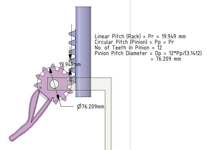
When the rack and pinion assembly is imported in SpaceClaim, we need to identify the pitch circle (or cylinder) of the pinion and the pitch line (or plane) of the rack. We then need to define “Gear Condition” between the cylinder and plane. The following diagram shows the equations for determining the pitch circle diameter of the pinion. Once it is found, a line tangent to this circle and parallel to the rack surface is the pitch line. The circle and line are then pulled to make surfaces, between which Gear Condition is defined.
In the video tutorial below:
- We have imported a Rack and Pinion Assembly from GrabCAD.
- Define revolute joint (consisting of Align condition + Tangent condition) between pinion and the base part.
- Define prismatic/translatory joint (consisting of Align condition + Angle condition) between rack and the base part.
- Determine the pitch circle of the pinion. Draw a line tangent to this circle and parallel to the rack surface.
- Make the circle and line as “Construction lines”, so that we can get surfaces when these are pulled. (which are without mass).
- Gear condition is defined between cylindrical and planar surfaces.
- Pinion is rotated about its axis and the rack translates due to proper meshing.
- Go to SC-Motion. Define joint rotation for pinion and its rotation results in the translation of the rack.
The SpaceClaim assembly file (with Gear condition defined) can be downloaded here.
The video tutorial can be downloaded here
We have similar tutorials for External Gears, Internal Gears, Worm Gears and Bevel Gears.
